Wiremap By Eli@liztechdata.com
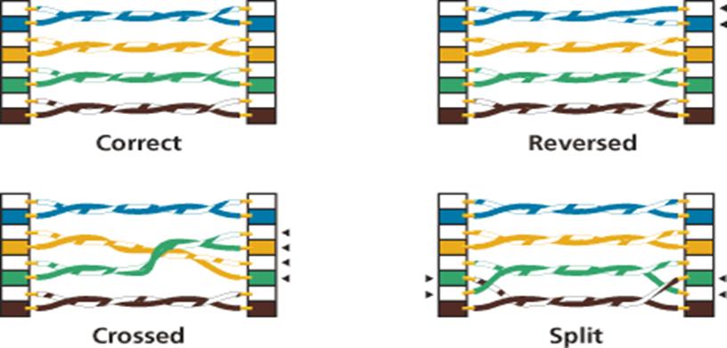
Wiremap is used to identify installation wiring errors. For each of
the 8 conductors in the link, wire map should indicate:
- Proper pin termination at each end
- Continuity to the remote end
- Shorts between any two or more conductors
- Crossed pairs
-
- Reversed pairs
- Shorted pairs
- Any other miswires
A
reversed pair occurs when the polarity of one wire pair is reversed at one end
of the link (also called a tip/ring reversal). A crossed (or transposed) pair
occurs when the two conductors in a wire pair are connected to the position for
a different pair at the remote connector.
Results
Interpretation
In most cases you will expect to see straight through connections. With simple
tools, such as LED display testers, a lamp will light up indicating a short or
open. Advanced tests, such as reversed or split pairs, are often not available
in such equipment. While these tools are usually adequate, it must be noted
that a passing result does not necessarily guarantee a correct wiring
installation. For example, split pair detection requires the measurement of
NEXT or Impedance, which is beyond the capability of low-end testers.
In the case of Screened Twisted Pair cabling you will need to verify screen
continuity. This is usually only available on more advanced certification
tools.
Wire map is a
fundamental test, but it is important to note that correct wiring does not
verify bandwidth performance. Frequency-dependent tests such as NEXT,
attenuation, and return loss are key to ensuring
cabling is capable of supporting high-speed applications.
Troubleshooting
Recommendations
In the
case of a wire map failure, a careful examination of the installation (IDC
block or connector) will usually show that one or more wires have been
transposed. Inspect and re-terminate as necessary.
If conductors
are missing, it could be because they are unnecessary for the intended
application. For example, 10BASE-T and token ring each require only four
conductors. Some wiring designs purposely use one four pair cable to supply two
RJ45 connections each with two pairs. The important issue is to ensure the
installed cabling meets the required design criteria.
If an open
conductor is found, use the length measurement capability of your cable meter
to determine whether the open is at the near or far end to speed fault
isolation and repair.
Length
Length
is defined as the physical or sheath length of the cable. It should correspond
to the length derived from the length markings commonly found on the outside
jacket of the cable. Physical length is in contrast to electrical or helical
length, which is the length of the copper conductors. Physical length will
always be slightly less than electrical length, due to the twisting of the
conductors.
To
measure length, a test set first measures delay, then uses the cable's nominal
velocity of propagation to calculate length. Nominal Velocity of Propagation
(NVP) refers to the inherent speed of signal travel relative to the speed of
light in a vacuum (designated as a lower case c). NVP is expressed as a
percentage of c, for example, 72%, or 0.72c. All structured wiring cables will
have NVP values in the range of 0.6c to 0.9c. Similarly, if you know the
physical length and the delay of a cable you can calculate the NVP.
In
most instances, length is derived from the shortest electrical length pair in
the cable. Because of delay skew, the length of the four pairs often appears
slightly different. This is normal and no cause for concern with the
exception of significant (over 10%) variances.
Results
Interpretation
The main concern when measuring length is that there is not a lot of cable in
any segment. For horizontal structured cabling this means 100 meters. This is
because applications have been designed to support a maximum signal propagation
delay, and if the link is too long, this delay could be exceeded. Occasionally
installers may leave excess cable in the ceiling or wall in anticipation of
future needs. While this is okay if it is considered part of the overall
run, tightly coiling excess cable can lead to undesirable performance
degradation due to additional return loss and near end crosstalk.
Troubleshooting
Recommendations
One of the most common reasons for failing length on a test is that the
NVP is set incorrectly. If you are not careful and use the preset cable
type it may not match the NVP of the cable under test. In this case, you can
have an NVP difference of 10% or more, which translates directly into a length
error. In the event the length is only slightly too long, check the NVP and
cable type.
Assuming the NVP
is correct, another cause of excess length is extra cabling looped in the
ceiling or walls. Does the link in question meet the anticipated plan? For
example, in the case of an airline hanger or warehouse, a remote station may be
forced to be over 100 meters from the wiring closet. If this has been planned
for, and the intended application supports the excess length, then the link may
fail structured wiring standards but still be approved for the application.
Some field testers allow customized autotests to be
configured that permit variances from standard TIA and ISO/CENELEC
requirements. Such autotests are useful because they
verify the installation meets requirements while allowing for planned
variances.
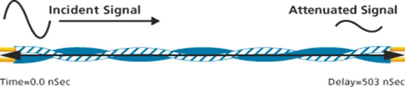
Propagation Delay
Propagation
delay, or delay, is a measure of the time required for a signal to propagate
from one end of the circuit to the other. Delay is measured in nanoseconds (nS). Typical delay for category 5e UTP is a bit less than 5 nS per meter (worst case allowed is 5.7 nS/m). A 100 meter cable might
have delay as shown below.
Delay is the principle reason for a length limitation in LAN cabling. In many
networking applications, such as those employing CSMA/CD, there is a maximum
delay that can be supported without losing control of communications.
Nominal
Velocity of Propagation (NVP) on the other hand, is different. NVP refers to
the inherent speed of signal travel relative to the speed of light in a vacuum
(designated as a lower case c). NVP is expressed as a percentage of c, for
example, 72%, or 0.72c. All structured wiring cables will have NVP values in
the range of 0.6c to 0.9c.
Results
Interpretation
Delay measurements are relatively straightforward. Most structured wiring standards
expect a maximum horizontal delay of 570 nS. If
design specifications allow, higher delay can be acceptable.
Since each pair
in the cable has its own unique twist ratio, the delay will vary in each pair.
This variance (delay skew, discussed in the next section) should not exceed 50 nS on any link segment up to 100 meters. Standards require
all pairs to meet the requirement. It is possible to report just the worst case
pair. This will be the pair with the highest propagation delay.
Troubleshooting
Recommendations
Excessive propagation delay can have only one cause: the cable is too long. If
you fail propagation delay, check to ensure that the pass/fail criteria match
the design specifications. If so, the cable is too long. In many cases, a cable
up to 25% too long (125m for Category 5) will still support most LAN
applications. However, the installation will fail most structured wiring
standards, such as those published by CENELEC, ISO/IEC, and the TIA. In some
cases, if the customer insists on the location of the terminal equipment, and
an excessive length cannot be avoided, you can verify other cable parameters.
If they pass, you can provide information that indicates the cable meets
frequency-dependent parameters but is non-compliant with overall standards due
to excessive length. This provides professional results to the user while
placing on them the responsibility for non-compliant cabling.
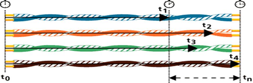
Propagation Delay Skew
Propagation
Delay Skew (skew) is the difference between the propagation delay on the
fastest and slowest pairs in a UTP cable. Some cable construction
employ different types of insulation materials on different pairs. This
effect contributes to unique twist ratios per pair and to skew.
Skew
is important because several high-speed networking technologies, notably
Gigabit Ethernet, use all four pairs in the cable. If the delay on one or more
pairs is significantly different from any other, then signals sent at the same
time from one end of the cable may arrive at significantly different times at
the receiver. While receivers are designed to accommodate some slight
variations in delay, a large skew will make it impossible to recombine the
original signal.
Results
Interpretation
Well-constructed
and properly installed structured cabling should have a skew less than 50
nanoseconds (nSec) over a 100-meter link. Lower skew
is better. Anything under 25 nSec is excellent. Skew
between 45 and 50 nanoseconds is marginally acceptable.
Troubleshooting
Recommendations
If the
skew is high, provided the intended application is a
2-pair application such as 10Base-T or token ring, the application should still
perform. If one pair is much higher or lower in delay than the others, very
high skew may result. Examine the delay results for each pair. If one pair
exhibits uncharacteristically high or low delay, re-examine the installation.
Attenuation
Recent
changes in the standards now use the term "insertion loss" and not
attenuation. Given that test equipment manufacturers have used the
term attenuation since 1993, attenuation will continue to be seen on test
reports.
Electrical
signals transmitted by a link lose some of their energy as they travel along
the link. Insertion loss measures the amount of energy that is lost as the
signal arrives at the receiving end of the cabling link. The insertion loss
measurement quantifies the effect of the resistance the cabling link offers to
the transmission of the electrical signals.

Insertion
loss characteristics of a link change with the frequency of the signal to be
transmitted; e.g. higher frequency signals experience much more resistance.
Stated a different way, the links show more insertion loss for higher frequency
signals. Insertion loss is therefore to be measured over the applicable
frequency range. If you test the insertion loss of a Category 5e channel, for
instance, the insertion loss needs to be verified for signals ranging from 1
MHz to 100 MHz. For Cat 3 links the frequency range is 1 through 16 MHz.
Insertion loss also increases fairly linearly with the
length of the link. In other words, if link "A" is twice as long as
link "B", and all other characteristics are the same, the insertion
loss of link "A" will turn out twice as high as the insertion loss of
link "B."
Insertion
loss is expressed in decibels or dB. The decibel is a logarithmic expression of
the ratio of output power (power of the signal received at the end of the link)
divided by input power (the power launched into the cable by the transmitter).
The table below demonstrates that the decibel scale is not a linear scale.
Results
Interpretation
The attenuation in a cable is largely dependent upon the gauge of wire used in
constructing the pairs. 24 gauge wires will have less attenuation than the same
length 26 gauge (thinner) wires. Also, stranded cabling will have 20-50% more
attenuation than solid copper conductors. Field test equipment will report the
worst value of attenuation and margin, where the margin is the difference
between the measured attenuation and the maximum attenuation permitted by the
standard selected. Hence a margin of 4 dB is better than 1 dB.
Troubleshooting Recommendations
Excessive length is the most common reason for failing attenuation. Fixing
links that have failed attenuation normally involves reducing the length of the
cabling by removing any slack in the cable run.
Excessive
attenuation can also be caused by poorly terminated connectors / plugs. A poor
connection can add significant attenuation. Your clue to this cause is to
compare the attenuation on the four pairs. If only one or two pairs have high
attenuation, this suggests an installation issue. If all pairs have too much
attenuation, check for excess length. However, impurities in the copper cable
can also cause attenuation failures; again this typically happens on one pair
only.
Temperature
also affects attenuation in some cables. The dielectric materials, which form
the conductor insulation and cable jacket, absorb some of the transmitted
signal as it propagates along the wire. This is especially true of cables
containing PVC. PVC material contains a chlorine atom which is electrically
active and forms dipoles in the insulating materials. These dipoles oscillate
in response to the electromagnetic fields surrounding the wires, and the more
they vibrate, the more energy is lost from the signal. Temperature increases
exacerbate the problem, making it easier for the dipoles to vibrate within the
insulation. This results in increasing loss with temperature.
For
this reason, standards bodies tend to specify attenuation requirements adjusted
for 20°C. Cables operating in temperature extremes can be subject to additional
attenuation and where this is likely, the design of the cabling system should
take this into consideration. You may not be able to run the maximum 90 meters
(295 ft) defined in the standards. Many consultants try and keep runs below 80
meters (262 ft) to provide a safety margin. This of course is not always
possible when space is a premium and the number of telecommunications rooms has
to be kept to a minimum.
Near End Crosstalk (NEXT)
When
a current flows through a wire, an electromagnetic field is created which
can interfere with signals on adjacent wires. As frequency increases, this
effect becomes stronger. Each pair is twisted because this allows opposing
fields in the wire pair to cancel each other. The tighter the twist, the more
effective the cancellation and the higher the data rate supported by the cable.
Maintaining this twist ratio is the single most important factor for a
successful installation.
If wires are not tightly twisted, the result is Near End Crosstalk (NEXT). Most
of us have experienced a telephone call where we could hear another
conversation faintly in the background. This is crosstalk. In fact, the name
crosstalk derives from telephony applications where 'talk' came 'across'. In
LANs, NEXT occurs when a strong signal on one pair of wires is picked up by an
adjacent pair of wires. NEXT is the portion of the transmitted signal that is
electromagnetically coupled back into the received signal.

Results
Interpretation
Since NEXT is a measure of difference in signal strength between a disturbing
pair and a disturbed pair, a larger number (less crosstalk) is more desirable
than a smaller number (more crosstalk). Because NEXT varies significantly with
frequency, it is important to measure it across a range of frequencies, typically
1 – 100 MHz. If you look at the NEXT on a 50 meter segment of twisted pair
cabling, it has a characteristic "roller coaster going uphill" shape.
That is, it varies up and down significantly, while generally increasing in
magnitude. This is because twisted pair coupling becomes less effective for
higher frequencies.
The field tester should compare successive readings across
the frequency range against a typical pass/fail line, such as the Class D
specification. If the NEXT curve crosses the pass/fail line at any point, then
the link does not meet the stated requirement. Since NEXT characteristics are
unique to each end of the link, six NEXT results should be obtained at each
end.
Troubleshooting
Recommendations
In many cases, excessive crosstalk is due to poorly twisted terminations at
connection points. All connections should be twisted to within 13 mm of the
point of termination according to ANSI/TIA/EIA 568-B. An additional note common
to all standards is that the amount of untwist should be kept to a minimum.
Experience has shown that 13mm does not guarantee a PASS when field testing.

The first thing
to do in the event of a NEXT failure is to use the field tester to determine at
which end the NEXT failure occurred. Once this is known, check the connections
at that end and replace or re-terminate as appropriate. If this does not appear
to be the problem, check for the presence of lower Category patch cords (such
as voice grade cable in a Class D installation). Another possible cause of NEXT
failures are split pairs. These can be identified automatically with the wiremap function of your field tester. Female couplers are
another high source of crosstalk and should not be used in a data installation.
If a cable is not long enough, replace it with a cable of the required length
rather than adding another cable.
Sometimes a NEXT
failure is caused by an inappropriate test being selected. For example, you
cannot expect a Category 5 installation to meet Category 5e performance
requirements.
The best method
for troubleshooting NEXT is to use a tester with Time Domain
capabilities. This gives the tester the ability to show the fault by
distance, pinpointing the problem. This diagnostic function clearly identifies
the cause of the NEXT failure, whether it's the patch cord, connection, or
horizontal cable.
In the event you
have eliminated all of the above NEXT sources and are still experiencing NEXT
failures, contact the system designer for further assistance.
Attenuation to Crosstalk Ratio (ACR)
Attenuation
to Crosstalk Ratio (ACR) is the difference between NEXT and the
attenuation for the pair in the link under test. Due to the effects of
attenuation, signals are at their weakest at the receiver end of the link. But
this is also where NEXT is the strongest. Signals that survive attenuation must
not get lost due to the effects of NEXT.
Using
PSNEXT and attenuation, Power Sum ACR (PSACR) can also be calculated. PSACR is
not required by TIA/EIA 568-B. Some field testers will report it anyway.
However, if you desire PSACR you will need to specify it's requirement in the statement of works document.
During
signal transmission over twisted pair cable, both attenuation and crosstalk are
active simultaneously. The combined effect of these two parameters is a very
good indicator of the real transmission quality of the link. This combined
effect is characterized by the Attenuation-to-Crosstalk Ratio (ACR). ACR is
nearly analogous to the definition of signal-to-noise ratio. (ACR excludes the
effect of external noise that may impact the signal transmission.)
Results
Interpretation
ACR is an important figure of merit for twisted pair links. It provides a
measure of how much 'headroom' is available, or how much stronger the signal is
than the background noise. Thus, the greater the ACR, the
better.
Troubleshooting
Recommendations
ACR is derived from NEXT and attenuation data. Any steps taken to improve
either NEXT or attenuation performance will improve ACR performance. In
practice, this usually means troubleshooting for NEXT because the only way to
significantly improve attenuation is to shorten the length of the cable.
Power Sum NEXT (PSNEXT)
Power
Sum NEXT (PSNEXT) is a calculation, not a measurement. PSNEXT is derived from
the summation of the individual NEXT effects on each pair by the other three
pairs. PSNEXT is important measurements for qualifying cabling intended to
support 4 pair transmission schemes such as Gigabit Ethernet, although IEE
8023.ab does not specifically require PSNEXT. If you run the specific Gigabit
Ethernet test within the field tester, you will see that PSNEXT is not recorded.
There are four PSNEXT results at each end of the link per link tested.
 Results Interpretation
Since PSNEXT is a measure of difference in signal strength between disturbing
pairs and a disturbed pair, a larger number (less crosstalk) is more desirable
than a smaller number (more crosstalk). Because PSNEXT varies significantly
with frequency, it is important to measure it across a range of frequencies,
typically 1 – 100 MHz. If you look at the PSNEXT on a 50 meter segment of
twisted pair cabling, it has a characteristic "roller coaster" shape.
That is, it varies up and down significantly, while generally increasing in
magnitude. This is because twisted pair coupling becomes less effective for
higher frequencies. Typically, PSNEXT results are around 3 dB lower than the
worst-case NEXT result at each end of the link.
Troubleshooting
Recommendations
Since PSNEXT is a calculation based on NEXT measurements, troubleshooting for
PSNEXT failures reduces to troubleshooting for NEXT problems. Once you have
isolated and repaired the NEXT problem, PSNEXT will automatically improve.
Troubleshooting NEXT requires a field tester with the ability to look down the
cable and see where the crosstalk is happening.
Power Sum Attenuation to Crosstalk Ratio (PSACR)
Power Sum
Attenuation to Crosstalk Ratio (PSACR) is actually a calculation, not a
measurement. PSACR is derived from an algebraic summation of the individual ACR
effects. There are four PSACR results at each end of the link per link tested.
Results
Interpretation
Since PSACR is a measure signal to noise ratio, a larger number (more signal
and less noise) is more desirable than a smaller number (more noise and less signal). Typically PSACR results are around 3 dB lower
than the worst-case ACR result at each end of the link.
Troubleshooting
Recommendations
Since PSACR is a calculation based on ACR measurements, troubleshooting for
PSACR failures is really troubleshooting for ACR problems. As mentioned
earlier, troubleshooting for ACR becomes troubleshooting for NEXT and
attenuation. Once you have isolated and repaired the ACR problem, the PSACR
will automatically improve.
Return Loss
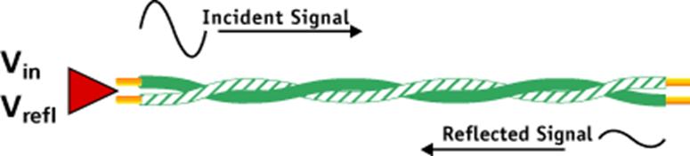
The
impact of incorrect characteristic impedance is more accurately measured and
represented by the quantity return loss.
Return
Loss (RL) is a measure of all reflections that are caused by the impedance
mismatches at all locations along the link and is expressed in decibel (dB).
Return Loss is of particular concern in the implementation of Gigabit Ethernet.
The
value of impedances at the ends of the link must be equal to the characteristic
impedance of the link. Frequently, this impedance is imbedded in the
interface of equipment to be connected to the LAN. A good match between
characteristic impedance and termination resistance in the equipment provides
for a good transfer of power to and from the link and minimizes
reflections. The return loss measurement varies significantly with
frequency. One source of return loss is due to (small) variations in the value
of the characteristic impedance along the cable. The property Structural Return
Loss (SRL) summarizes the uniformity in cable construction. SRL is to be
measured and controlled during the cable manufacturing process. Another
source is caused by reflections from inside the installed link, mainly from
connectors. The characteristic impedance of links tends to vary from higher
values at low frequencies to lower values at the higher frequencies.
Results Interpretation
All
standards define the formulae to calculate the
allowable return loss for each cabling link model (Channel and Permanent Link)
over the frequency range. A field test instrument may report a passing return
loss test result in one of two ways: (1) the
worst case return loss margin or (2) the worst case return loss value.
Troubleshooting
Recommendations
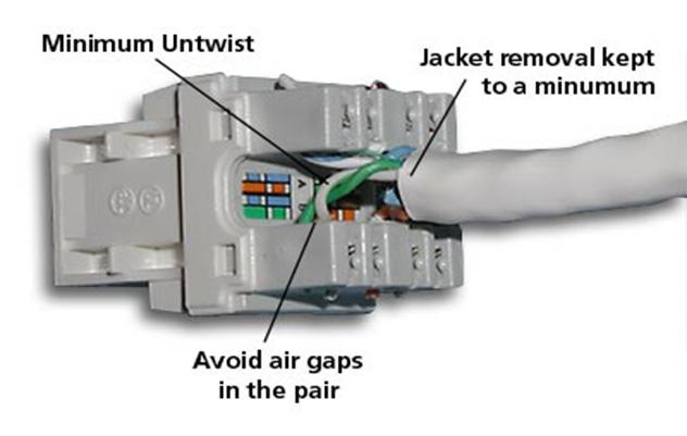
Installation practices are more important on Category 5e and 6 than they were
for Category 5. Additional unnecessary untwist in terminations can add
several dB of return loss in some cases. Below is an example of a correctly
terminated connector. Take note of the minimum jacket removal and twists being
maintained.
Be sure to apply a high level of care when installing
cabling that requires return loss qualification.
Far End Crosstalk (FEXT)
Far End
Crosstalk is similar to Near End Cross Talk (NEXT), except that the signal is
sent from the local end and crosstalk is measured at the far end.
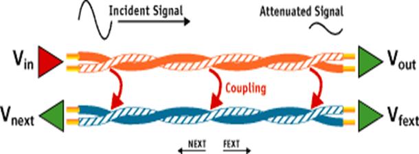
Because of
attenuation, signals that induce FEXT can be much weaker, especially for longer
cable lengths. This effect means that for a given quality of cabling, more FEXT
will be seen on a short link than a long link. For reason, FEXT results are not
meaningful without an indication of the corresponding attenuation on the link.
Thus, FEXT is measured but rarely reported. FEXT results are used to derive
Equal Level Far End Crosstalk (ELFEXT).
Equal Level Far End Crosstalk (ELFEXT)
ELFEXT
is a calculated result, rather than a measurement. It is derived by subtracting
the attenuation of the disturbing pair from the Far End Crosstalk (FEXT) this
pair induces in an adjacent pair. This normalizes the results for length.
Consider the FEXT and attenuation measured on two links constructed of the same
materials with the same workmanship, but different lengths.
50 m link example:
FEXT
= 45 dB and Attenuation = 11 dB
ELFEXT
= 45 - 11 = 34 dB
Another
way to understand ELFEXT is to think of far-end Attenuation Crosstalk Ratio
(ACR) as the same thing.

Results
Interpretation
Compare the results of measurements made from both ends of the link to the
appropriate ISO or TIA limits. There are 12 ELFEXT measurements made from each
end, for a total of 24. This is because the attenuation can vary slightly
depending upon which pair is energized. So as an example, the field tester will
energize Pair 1 and listen on Pair 2 at the far end. Then it will energize
Pair 2 and listen on Pair 1 at the far end.
ELFEXT that is
too high is indicative of either excessive attenuation, higher than expected
FEXT, or both.
Troubleshooting
Recommendations
The same factors that contribute to NEXT problems contribute to FEXT problems.
Troubleshooting for ELFEXT means troubleshooting NEXT and attenuation
problems, just as you would for ACR problems.
Power Sum Equal Level Crosstalk (PSELFEXT)
Power
Sum ELFEXT (PSELEXT) is actually a calculation, not a measurement. PSELEXT is
derived from an algebraic summation of the individual ELFEXT effects on each
pair by the other three pairs. There are four PSELFEXT results for each end.
Results
Interpretation
Typically PSELFEXT results are around 3 dB lower than the worst-case ELFEXT
result at each end of the link.
Alien Crosstalk
When cables are
adjacent to each other, emissions from one cable can affect pairs in the other
cables. This effect is called Alien Crosstalk. For UTP cables that are closely
bundled together for a distance of more than 15 meters, Alien Crosstalk can be
a concern. Alien Crosstalk, unlike NEXT, is an unpredictable noise source.
Measurement of alien crosstalk is difficult because it requires synchronizing
two sets of test instruments, and it is a lab measurement only. There are no
pass/fail limits proposed or set.
Insertion Loss Deviation
Impedance
uniformity is an increasingly important parameter to understand, measure, and
quantify for high speed full duplex transmission systems. The most common way
to specify cable roughness or impedance uniformity has been to measure return
loss. Since return loss is a reflection measurement, the amount of impedance
variation measured becomes restricted at high frequencies to the first few
meters of cabling. There is an interest in looking at the degree of impedance
uniformity over an entire 100 meter segment in such a way as the high frequency
components or roughness are not masked or attenuated by distance.
One
way to accomplish these objectives is to make a through measurement rather than
a reflection measurement. When insertion loss is measured on links exhibiting
structural impedance variations, a ripple occurs in the insertion loss results
at high frequencies (typically above 75 MHz). This ripple increases in
magnitude as a function of frequency and the amount of structure in the cable.
Insertion loss deviation is a measure of the worst case difference in magnitude
between the expected insertion loss and the actual measured insertion loss.
Insertion loss deviation is measured by first finding the insertion loss, and
then computing the maximum amplitude across the specified frequency range
between the insertion loss and the least squares curve that fits the insertion
loss data.
The
term "insertion loss" is used instead of attenuation because
attenuation assumes matching impedance between the system under test and the
test device. For insertion loss measurements the test device is set at 100 ohms
and the system under test may have an input impedance
between 85 and 115 ohms.
Experiments
show that return loss is not necessarily correlated to insertion loss
deviation.
Results
Interpretation
While insertion loss deviation is under study as a Category 6 link test, there
are as yet no pass/fail limits set. All that can be said is
the minimum possible insertion loss is desirable.
As an
illustration of insertion loss deviation, two Category 5 cables and one Category
6 cable were tested with a network analyzer. Attenuation and return loss were
measured, then insertion loss deviation computed. All
three results were plotted on the same graph to 300 MHz.
Category 5 cable
C shows a correspondence between an insertion loss minima at 112 MHz and a return loss maxima. The worst case insertion loss deviation on
cable C was slightly less than 2 dB. The worst case insertion loss deviation on
cable B was much worse, at 8 dB, yet cable B showed better return loss
performance. This suggests some structure effects are only evident at higher
frequencies. Because return loss is a reflection measurement, much of these
high frequency effects are not seen if they are more than a few meters from the
measurement port (due to attenuation effects).
DC
DC
Loop Resistance is the total resistance through two conductors looped at one
end of the link. This is usually a function of the conductor diameter and
varies only with distance. This measurement is sometimes done to ensure there
are no gross misconnections which can add significant resistance to the link.
Note that the wire map test automatically isolates breaks but not high
resistance connections.
DC resistance is often confused with impedance, a term describing the dynamic
resistance to signal flow, usually at a specified frequency. Both are measured
in ohms because they define different types of opposition to electrical current
flow. DC resistance increases proportionately with the length of the cable
tested while impedance remains "fairly" constant regardless of
length.
From
a signal perspective, attenuation (sometimes called insertion loss) is now a more useful measurement, and DC
resistance has become less important.
Results
Interpretation
Variations in loop resistance between pairs can often be a quick indication of
a cabling problem. In a shorted loopback test
environment, the expected value is simply twice the sum of the value expected
for the given length. This is a simple test for any advanced field tester.
Troubleshooting
Recommendations
In the case of unexpected high DC resistance, compare the failed pair against other pairs in the cable. This will determine
whether the issue is specific to the one failed pair or due to a problem affecting
the entire cable. If a single pair is at fault, inspect termination points for
a poorly made or oxidized connection.
If all four
pairs have unexpected high DC resistance, check your assumptions. Did you allow
for double the resistance to include the loopback? Is
the resistance assumption correct for the gauge of wire used? 26 gauge has higher resistance per foot than 24 gauge. Do you
have an unusual patch cord in the link that could have high resistance? Look
for anything unusual especially if adjacent cables appear to be normal.
Our Services
 Data Voice Cable install in edmontonLizTech Data commercial residential Data Voice fiber structured cabling Edmonton AB, Edmonton structured cabling, CAT 5, CAT 6, fiber optic, install VOIP phone systems, network wiring, Network Services Contractor install Telephone Systems, Cable Removal relocates, Services Cable Testing, Fiber Optic, Testing Fiber, Installations Cabling CAT5 CAT5E CAT6 CAT6A FIBER RJ6 RJ11, 25par CAT3, 100 par CAT3 , security cameras and more
 We Do Have IT DepartmentWe can fix any computer / server problems, softwhere problems, install wireless network, install switch modem, fire wall, Ups, install operation systems. win98, winxp, win 2000, win 2003 server, win 2008 server, and more
LiztechData offers computer repair, service, virus removal, and laptop repair and computer support build custom servers windows 311 to windows 7
Servers win NT4 to Windows 2010 server
 web designs and hosting email host & files host we can get your site up and fast we can host build.
 We have special knowledge about all phone system computers and the new technology
We do install cell phone towers get you the crew to work with you for everything you need we work all over Canada
DEC home security solutions home alarm monitoring service this constant monitoring ensures a quick response for any home security emergency.
DEC business or commercial property safe with an alarm system and enhanced monitoring services. notifications, camera systems and controlled access for complete commercial security solutions
You need to see
Our focus is your business and your job site your IT will love the job and the equality we know that we are the best company for you so don't wait call us for Quote there is no Big Job for Us Our estimator will love to give you hand in the data voice TV fiber cable info cat 3 to cat6 we provide 25 warranty.
I thank you for taking the time to read about us and about the company's i did comment on
If you need more info you can call us or drop emailThanks Eli Hagage
working with the top